|
Introduction
GeoTracer is one member of the Geomet Suite of Reverse Engineering Tools. GeoTracer is
designed to capture large amounts of data points using a hard ball probe by dragging the
probe over a surface expanding the usefulness of your manual Coordinate Measuring Machine.
Command Activation:
| |
Measure→GeoTracer |
|
| Keyboard |
Main Menu |
Toolbar |
When activating the GeoTracer tool, you will be presented with a parameter dialog which
you set the performance characteristics, see figure 1.
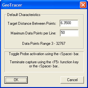 |
| figure 1, GeoTracer Parameters |
Target Distance Between Points:
The value entered becomes the length Geomet will use to establish the
minimum distance between data points. When GeoTracer is in motion, the CMM
sends a constant stream of data points to Geomet. The first data point
captured will be stored and all incoming data points will be compared to the
first point until the distance between points exceeds the target distance.
Once that minimum distance has been met, the second point will be captured
and the process repeats itself.
Maximum Data Points per Line:
The value entered here will limit the size of a single data cloud that is
stored as a single feature. Once the data cloud size equals this value,
Geomet will create a new feature in the inspection report that contains the
captured data points. Geomet will then recycle the GeoTracer allowing you to
continue capturing data without stopping. The purpose of limiting your data
cloud size is only for convenience to limit how much data will be included
in one feature.
Capturing Data with GeoTracer
When you compete the GeoTracer parameter dialog, you will be prompted to capture data
points, see figure 2.
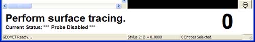 |
| figure 2, GeoTracer Prompt |
Once the prompt appears, the capturing of the data points is suspended allowing you
time to move the CMM into position on your part. This is indicated by the
Probe
Disabled statement next to the Current Status prompt.
When you are ready to capture data, press the space bar, or depress the optional foot
switch. Geomet will capturing data when you start moving your probe across the part.
Pressing the space bar again will cause Geomet to return to a Disabled Probe state and
create a feature based on the captured data point count.
Capturing Data with GeoTracer on DCC style CMMs
The GeoTracer tool can be used on DCC style CMMs as long as you can disable the motion
drive system. To disable the motion drive system within Geomet, activate the System
Options <F9>, see figure 3.
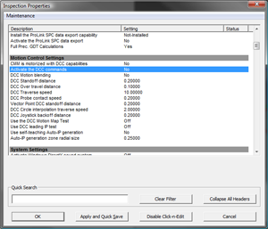 |
| figure 3, Activate DCC Commands |
As shown in figure 3, the setting "Activate the DCC commands"
is highlighted. Change the setting to 'No' and press
<Ok>. You can now change your probe system by installing the hard probe to be used
by GeoTracer and follow the GeoTracer instructions.
The Captured Data Cloud
The data points being captured will be the XYZ location of the probe ball center. Since
probes do not offer vector feedback informing the host measuring software where the
contact point was on the ball, a determination of surface points is not possible. This
condition can be corrected by exporting the data clouds to most of the popular CAD systems
and then constructing a surface followed by offsetting a surface by the probe radius.
Useful Tips
If your intent is to take the data clouds and export them to a CAD
system, it is helpful to organize how you capture the data clouds. Most
manual CMMs offer locking mechanisms on the X, Y and Z-axes. This allows you
to lock one axis and drag the probe over your part to form a single line of
data points. When you reach the end of your captured data point line, press
the <space bar>, this will create a feature in the inspection report. Next,
remove the lock and move to a new location and reset the lock repeating the
drag operation to create a parallel set of data points.
Cardinal Spline
The Cardinal Spline tool will create a fitted spline through your data points which
offer a smoother transition for the CAD system to fit a surface to the data points you
captured. See Cardinal Spline for detailed usage.
Performance Issues and GeoTracer
The quality of the data points can be affected by the speed of the CMM
while capturing the data points. A CMM interface captures the XYZ scale
values based on a timed cycle. Some interfaces cycle 30 times or more per
second, such as the Helmel ProCounter series. At this cycle speed you will
capture a consistent set of data points while dragging your hard probe at
normal speeds between 2" (51mm) and 5" (127mm) per second which translates
to capturing approximately 20-50 points per second.
If your CMM interface cycles at a lower rate, such as most interfaces on
Direct Computer Control (DCC) CMMs, the cycle can be slowed down to as
little as 3 cycles per second. On this style CMM the actual reading of the
XYZ scales is performed by the motion controller and forwarded to the host
measuring software as a status update. At the slower cycle rate, the drag
speed required to produce a uniform set of data points must be reduced to
speeds around 1" (25mm) per second.
Should the drag speed to fast the spread between data points will be
greater than the requested distance set in the GeoTracer Parameters. If you
find undesirable results in the spread of your data points, slow down the
drag speed.
Related Procedures:
Cardinal Spline,
Select Scan Method,
4-Point Boundary Scan,
Radial Boundary Scan,
Line Scan,
Export Tool
|


