Geomet can export features and data points in three
formats.
ASCII and DXF: Exports data point clouds and 3D Point
entities. On features, such as a circle, only the data points used to
calculate the feature would be exported.
IGES: This format exports all features based on the
following table.
|
Summary of IGES Supported Features |
|
Type |
Definition |
|
100 |
Circular Arc Entity |
|
104 |
Conic Arc Entity |
|
108 |
Plane Entity |
|
110 |
Line Entity |
|
116 |
Point Entity |
|
126 |
Rational B-Spline
Curve Entity |
|
128 |
Rational B-Spline
Surface Entity |
|
144 |
Trimmed (Parameteric)
Surface Entity |
|
158 |
Sphere Entity |
|
190 |
Plane Surface Entity |
|
196 |
Spherical Surface
Entity |
|
504 |
Edge Entity |
|
508 |
Loop Entity |
|
510 |
Face Entity |
Exploring the Export Tool
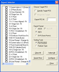
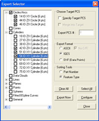
The Export Tool displays a feature list of your current
inspection. This list can be sorted between Part Number or into common
feature groups such as Circle and Planes.
Selecting Features for Exporting
Selecting features can be done in a random fashion by
placing a check next to the feature or by using <Select All> to
select all features. When sorted by Feature Number, the selection
process is accomplished on a feature-by-features basis by placing a
check next to the feature. When sorted by Groups, the selection process
can be done on a single feature basis by expanding a group using the "+"
button and checking the feature. To select all features within a group,
place a check next to the group name.
Setting the Decimal Precision
Setting the precision is done through the <Configure>
button. Always set a reasonable precision that will allow a well-defined
exported feature. The default for this value is 5.
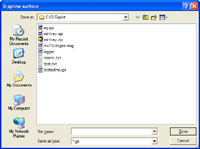 |
| Save Dialog |
Basic Export
With the selection of features, you can now proceed to
the export function. Press <Export> and the standard Windows
Save-As dialog will appear. Locate the folder and assign a file name to
your export and press <Save>.
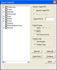
Enhanced Export Tools
There are two options available that will enhance the
exporting of features. These options control the Part Coordinate System
during the export process.
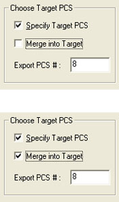 |
| PCS Target Tools |
Under normal conditions, all features are exported in
the original position within the CMM envelope, commonly referred to as
the Machine Coordinate System. All features will retain the position and
orientation to other features and in most cases this is sufficient.
However, you may want to export into a specific PCS making the position
and orientation local to the inspected part.
Specify Target PCS: This option allows a PCS to
be specified that all features would be projected into. This is commonly
used when you want a coordinate system locally on your part. When
exported the misalignment to the MCS is removed and the exported
features are aligned true to the selected PCS.
Merge into Target: This option allows merging of
all features that were originally built in other PCSs into a common PCS
for export. The result is an assembly that can combine all features into
a single file. Those features may have been measured on the side, bottom
or any orientation on the part