Geomet Versions - 6.66.006.001
The U/V Rotary Table must be calibrated before it can be
used. This is accomplished by performing a series of measurements on a
sphere in five locations that will identify the rotational characteristics. Geomet
will calculate the rotary axis and directions and save this information in
it's System Options for retrieval.
To start the setup process, ensure the rotary table is securely fastened
to the CMM table. Movement of the rotary table will only lead to poor
calculations when used in the inspection process.
To begin the setup routine, from the main drop down menus choose:
[System® U/V Rotary Table Tools®
Setup U/V Table Geometry]

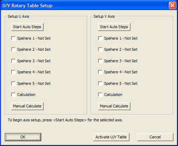
The setup tool will step you through a series of measurements for the
selected axis. To begin the process, press <Start Auto Steps>
for the chosen rotary axis. A message will appear indicating you are about to
start the setup process.
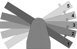
Using the U-Axis for our example, rotate the axis until the front of the
rotary table is all the way down. The setup sphere that is mounted on the
frame is then at its lowest position. Geomet will prompt you with a message:
Measure data point 1 of 5 on Sphere 1
 Each
sphere will require five data points. Four data points captured around the
equator and one on top. When you have completed capturing the five data
points, rotate the table upward about halfway between the current location
and its level position. Continue capturing five data points on each sphere
location until all five spheres have been measured, see illustration.
The setup tool will place a check next to the most recent completed sphere.
If you capture an errant data point, press the <
 Take Point> button on the joystick.
To ensure the greatest success, always spread your five spheres out to
the full extent of rotational travel.
Geomet will calculate the rotational axis geometry and save that
information to be recalled and applied to your measurements.
When the U-Axis setup procedure has been completed, return the rotary
table level with the CMM table. Repeat the setup process for the V-Axis by
pressing the <Start Auto Steps> button under Setup V-Axis
group.
A message will appear indicating you are about to start the setup process.
Upon accepting the message, Geomet will prompt you:
Measure data point 1 of 5 on Sphere 1
Rotate the V-Axis to a position that represents the extreme position to
the clockwise rotation that allows the CMM probe to access the sphere.
Capture the five data points and then rotate the V-Axis counter clockwise to
a new position and repeat the data point capturing. When finished with all
five sphere positions, Geomet will calculate the rotational axis parameters.
The U/V Rotary Table setup is now completed.


