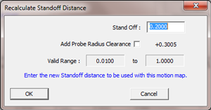
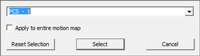
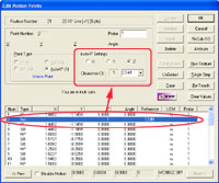
This feature will adjust all SO-MP-SO relationships. When you build the motion map the
first time, the current stand off distance established in DCC Settings will be used to
calculate the distance between the SO and MP and back-off SO. Using this feature allows you
to update all SO-MP-SO triplets with a new value.
For example, if you taught the motion
path with a standoff of 0.200", you can change that distance to 0.100" with this
feature. There exists one rule when using this tool, the MP must be bracketed by a leading
SO and followed by a SO.
On Geomet self-taught and older versions of Feature Generators, the SO and MP positions are stored as stylus center point. Newer generations now use surface MPs when created with Feature Generators. The SO positions remain stylus center. To accomodate a proper calcultaion for SO, an optional "Add Probe Radius Clearance" check is provided. Using this will ensure that the distance from the stylus to the surface remains as the full SO distance.

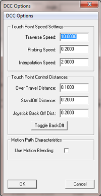
Through the use of this feature you can insert changes in both traverse
and measurement speeds as well as over travel distance. These changes are
implemented where they exist in the motion path until another attribute is
encountered.
For example if you have a motion critical area on your inspection piece
that requires the CMM to capture the MP at a more controlled slower rate,
Highlight the SO before the MP and use the <Attribute> command. Enter the
new lower speeds for Traverse and Probing and press <Ok>. A new motion
record will be inserted before the highlighted SO and has the Type ID “ATT”.
NOTE: Changes to Attributes remain active until another Attribute has
been encountered. You may elect to insert another Attribute when finishing
your critical MP to return to normal speeds.

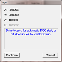
The Run Feature function will execute the motion path from the point of highlight. For
example, if step number 1 is highlighted, Geomet will prompt you move to a safe location
with a targeting box. When you press continue, Geomet will run all motion, including MPs
through the end of the motion map. If your highlight was on step 5, the motion will start
with that step.

The Single Step function will execute motion for just that one
highlighted step. The motion will occur for all IP, SO and Auto-IP records
and will not execute MPs. If the motion record has a XYZ location beyond the
in position limit, then the Target DRO (see Run Feature) will appear and the
operator then has the choice to manually move to the target position, use
move to the location under DCC control. This added step is used to prevent
potential CMM crashes if the requested location is at a distance from the
current probe location.
When you highlight the leading SO, motion will take place to the XYZ
location of the SO. Pressing single step again will skip through the MP and
move to the trailing SO for that MP. The single step feature is the tool
used most to correct any motion path concerns.

In the Re-Teach function, you can highlight a location in the motion map, press <Re-Teach> and from that point down teach a new motion path creating new IPs, and
MPs. This function is most useful when your part program has changed and you require major
changes to the motion path for the selected feature.
 |
 |
| Start ReTeach |
End Position |
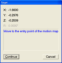
When starting the re-teach process, Geomet will display
the targeting dialog that shows the last location in the motion map.
This becomes you start position in your re-teach process. Manually move
to this location and press <Continue>. From this point, you would create
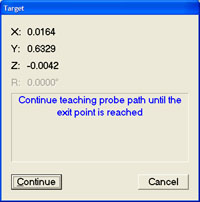
your new motion. A new target dialog will replace the start target
dialog and this new target is the next known location in your motion
map. This target will assist you in developing the new motion map. As
you re-teach your finish should be near this end location for smooth
transition between motion maps.

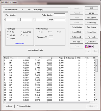
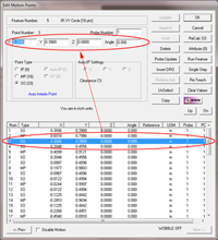
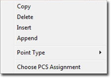
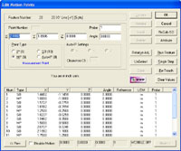
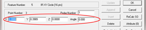
The <Update > command is used to revise selected entries in your Motion
Edit Tool. To edit an XYZ location of an IP/SO or MP, first highlight that point in the
motion map list. Its XYZ values will transfer into the edit control, see
example.
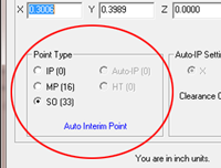
Edit the XYZ location values and commit the change by pressing <Update>.
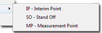
During the update process you can change the Point Type designation by
changing it from a IP to a SO, or any Point Type.
NOTE: Remember to press <Update> before selecting another motion map
record!
Tip: Not only can you Update existing features, but you may want to
insert a new motion map record using this process. To do this, highlight the
selected record and make any changes as needed to the XYZ location, then
press <Insert> and a new record will be placed before the highlighted
record.

As it sounds, the Append feature attaches a new motion map entry based on the values in
the XYZ edit controls to the bottom of the motion map. The type of point, IP, SO, etc,
will be assigned based on the current selection under Point Type.

This feature will insert an entry in the motion map, just above the current highlighted
entry. The new record will reflect the current values in the XYZ edit controls and Point
Type.

This feature deletes the current highlighted entry in the motion map.

To move your entire motion map a specified distance, enter a relative
distance in the XYZ edit controls. For example if you need to move the
motion map 0.025” in the X-Axis to compensate for a part change, enter
X=0.025, Y = 0.0, Z = 0.and press the <Relative Adj.> button. Your entire
motion map will be offset by 0.05, 0.0, 0.0.
NOTE: In some cases the leading IPs should not be adjusted. The motion
path that leads from the previous feature, to the start of the current
feature should be reviewed carefully to ensure a relative adjustment does
not cause unexpected motion.
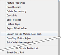
Geomet offers a single tool, One-Step Motion Edit, that
allows a relative motion adjustment to the entire motion map while protecting the leading
IPs.

This feature will drop the highlight in the motion map and clear all values in the XYZ
edit controls.

This feature takes the current highlighted motion map entry and places a copy in a
buffer. Once the record is in the buffer you can Append, Insert or Update
based on the following table:
| Copy
Functions |
| Append |
Pressing the <Append> button will attach a new motion record at the
end of the current motion map based on the copied record. |
| Insert |
Highlight a location in your motion map and select <Insert>. A new
record is created and inserted before the highlighted record. |
| Update |
Highlight a record in your motion map and press <Update>. The copied
record will replace the highlighted record. |

This will clear out all values in the X, Y, Z and Angle edit controls.

When you select to Disable Motion on the current feature,
Geomet will drop into manual mode during the part inspection for this feature. This allows
the operator to capture data points for the selected feature under Joystick or manual
operations.
When the feature is completed, Geomet looks at the next feature and if it is required
to return to DCC control, a targeting window is displayed to let the operator know where
the next DCC point will start.
For a more detailed explanation, see Disable
Motion.