| |
|
| |
Introduction |
| |
Cradle Definitions are the buttons the operator would
press to launch an inspection. Each button in defined
individually and are built on the Fixture Base
Definition. One easy way to visualize a Cradle
Definition System is to think of an egg carton we buy at
the local store. It commonly has 12 eggs in a 2 row by 6
column package. Each egg cradle has the same shape and
size, but a different location in the carton. The
overall carton is your Fixture Base Definition. The
individual egg compartments is the Cradle.
To
build a efficient EZ Launch Menu that your operators can
use, buttons are provided that contains all the
necessary information Geomet needs to commence a
inspection run. |
| |
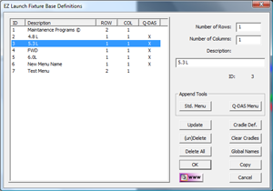
Activating the Cradle Definition Tools |
| |
Activating the Cradle Definition Setup Tool is
accessed from the Fixture Definition when you
created or are editing an existing menu.
Press the <Cradle Def.> button
to advance to the Cradle Definition Tool. |
 |
|
| |
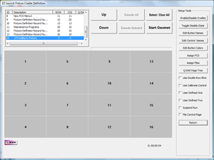
Cradle Definition Tool |
| |
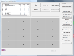
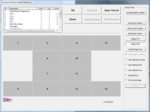
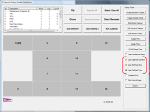
The Cradle Definition Tool is the same menu page
displayed by Geomet the operator would use in normal
inspection operation. While in the edit mode column of tools
is displayed to the right of the button, see
figure at right.
|
 |
|
| |
Customizing the Button Layout |
| |
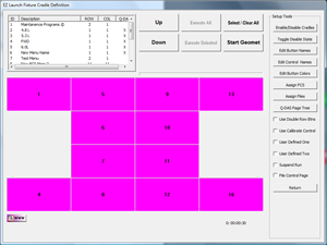
As shown in the image above, the Fixture is
defined as having 4 rows and 4 columns. In our
application we will only be using 12 total
cradles based on a 4-2-2-4 top to bottom layout.
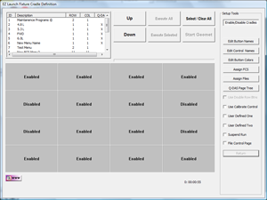
To remove the unneeded buttons use the
<Enable/Disable Cradle
Buttons> found in the edit tools
When you press in this tool,
the full layout of all buttons is displayed and is
labeled "Enabled" or "Disabled"
depending on current state. Toggle the
state by left-clicking on each button. When you
completed the selection, press the
<Enable/Disable Cradle Buttons> button again to
release the edit mode. |
 |
|
| |
|
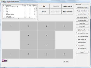
The end result is the buttons tagged as
"Disable" will not appear in the final menu. |
 |
|
| |
Assigning a Name to a Button |
| |
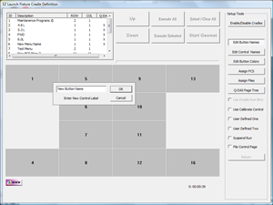
The default name attach to every button is it's
position number in the row/column array.
However, this is not very descriptive for
defining the button.
To assign a new name
to a button, choose the tool
<Edit Button Names>. To
edit the name of a button, left-click on the
corresponding button and a small control will
appear where you can enter a new name.
To
commit your changes, press <Edit
Button Names>
again. The Edit Button Command will only work on
the buttons located in the Row/Column
configuration and not the Control Buttons.
NOTE: Long names will be truncated to
fit the button. |
 |
|
| |
Assigning a Name to a Control Button |
| |
This command works exclusively on the Operator Level buttons:
- User Defined #1
- User Defined #2
- Execute Selected
- Execute All
- Start Geomet
- Run Calibrate
- Return
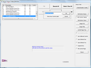
To change the button name, press the
<Edit Control Names> button, followed by a
left-click on the button whose name you want changed. Enter the new name and
press
<Edit Control Names> again to commit the new
names. A more detailed discussion of control names are provided on the
Global
Names Tool.
NOTE: Each Fixture Definition, or menu,
can have its own unique names applied to the
Control Buttons. By default, when the menu is
created, the names are assigned from the default
names found in the Global Names Tool. |
 |
|
| |
Assigning a Color Properties to the Buttons |
| |
The selection of the color for all buttons both
in the selected and non-selected state are
provided as standard Windows button for
non-selected and green for selected.
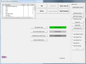
To change the button
colors, press the tool
<Edit
Button Colors>. The button layout changes to
show 4 color control buttons along with the
current colors.
NOTE: Color
selections are global to this menu page and are
not customized down to the individual button. |
 |
|
| |
Setting the color for a selected button |
| |
|
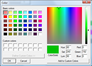
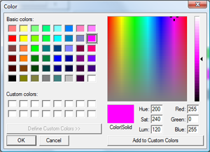
To change the color of a selected button, press
the button <Set Selection Color>.
The standard Windows color selector is
displayed. Choose the new color and accept with
the <Ok> button. |
 |
|
| |
Setting the background color for the buttons |
| |
To change the
background color of all buttons, press
the button <Set Top Row Button Color>.
The standard Windows color selector is
displayed. Choose the new color and accept with
the <Ok> button.
NOTE: EZ Launch Standard Menus can be
configured to provide upper/lower button
configurations in version 7.01.183. In future
releases of Geomet, this option will be
eliminated. |
 |
|
| |
Resetting all colors |
| |
To
reset all colors , press
the button
<Reset to Default Colors>. |
|
|
| |
Saving your color selections |
| |
|
To
commit the color changes, press the button <Edit
Button Colors>. |
 |
|
| |
Assign a Predefined Fixture Coordinate System (FCS) to a
Cradle |
| |
Assigning a unique Fixture Coordinate System
(FCS) to a cradle ensures that Geomet will have
the necessary information to know the location
and orientation of the cradle within the
MCS.
The benefit of using FCS
assignments is the ability to dynamically pass
the cradle’s FCS assignment into the part
inspection program for proper motion. For
example, if the part being inspected was
originally taught in cradle position #1 using
FCS #1, all motion in the inspection file is
referenced to FCS #1.
To utilize other
cradle positions we must inform the inspection
program what cradle the production part is now
residing in. This is done through the use of a
FCS.
Simply put, write one inspection
program and then use it in any cradle location
without manually teaching or transforming the
motion path.
When the inspection program
is executed, the first operation is to recall an
FCS, then commence the steps to measure the
part. To work with multiple Cradle positions,
the inspection program must be able to accept an
optional parameter that will change the assigned
FCS dynamically at inspection time. This is
referred to as a Dynamic FCS Assignment. |
 |
|
| |
Step 1—Assign a FCS to a cradle |
| |
To summarize, there are two steps required to
complete assigning an FCS. Start the edit tool
by pressing the <Assign FCS>.
NOTE: The FCSs to be referenced must
exist from previously being built on the
individual cradles.
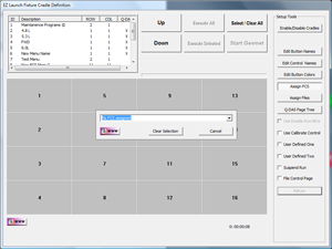
Assign an
existing FCS to a cradle with a left-click over
the cradle button. A drop down tool that lists
all available FCSs will appear, see example
at right. Open the drop-down tool by
left-clicking on the down arrow. Choose the FCS
to be assigned to this Cradle. Repeat this
procedure for all Cradles within your Fixture
Base Definition.
When you are finished
assigning FCSs, press the
<Assign FCS> button to lock in your
changes. |
 |
|
| |
Step 2—Edit the inspection program |
| |
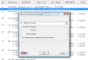
The last step is to edit your existing
inspection program. Locate the Recall FCS action
statement, and right-click to activate the FCS
edit tool, see figures at right.
Place a check next to
Dynamic
Fixture Assignments (Ez Launch Menus).
Press <Ok> to
save the change into the recall FCS record.
Save your inspection
file to commit the change.
This single
check commands Geomet to use the Cradle FCS
definition at run time.
NOTE: During
the inspection run, Geomet will identify whether EZ Launch menus opened the part
inspection and commenced the inspection run.
When this condition exists, the FCS will
dynamically update with the assigned FCS from EZ
Launch. Should the inspection program have been
opened through the [File→Open] command, the FCS
will not dynamically update. |
 |
|
| |
Assign
Inspection Files to a
Cradle |
| |
Each Cradle can have one or more inspection
programs assigned to it. You may also assign the
same inspection program to several Cradles.
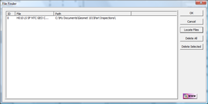
To assign files, press the tool
<Assign Files> and left-click on the
Cradle button to activate the File Finder tool,
see figure at right.
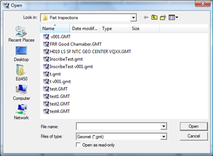
There are
three commands within the File Finder Tool.
Locate Files: This command launches the
standard Open Files navigation tool supplied
within Windows. Select one or more files to be
attached to the selected Cradle button. The
selected files can come from various directories
and you can return to the Locate Files command
to add additional files at any time.
Delete All: This command removes all assigned
files from the Cradle button.
Delete
Selected: When you have one file selected in the
File Finder tool, press <Delete
Selected> and the file is deleted from
the Cradle button.
NOTE: The Delete
commands only removes the assignments to the
Cradle buttons, it does not remove the file from
your hard drive storage. |
 |
|
| |
User Defined Buttons |
| |
The Cradle Definition Tool provides three
buttons that are used for accessing a single
part inspection, Re-Qualification or FCS Update
program.
They buttons are labeled:
- Run Calibration
- User Defined #1
- User Defined #2
These buttons are activated by placing a
check next to the button in the tools column,
see figure at right.
You can
assign a single part inspection program to any
of the
buttons, however these button do not support dynamic FCSs.
These are designed for single run applications.
For example, your quality plan may require that
the the active styli should be re-qualified
once per shift. We recommend that a
re-qualification program be written, see
Re-Qualify and
example, then assign that stored program
against the button using the
routine.
The User Defined buttons can be
reserved for programs that run a Fixture rebuild
program. The options are limitless as to the
usefulness of single touch button providing
access to any inspection program. |
|
|
| |
|


