The Ellipse feature determines the center location, Major Axis Rotation
and the Minor and Major diameter or radius of inside and outside ellipses projected into a PCS
base plane. The ellipse feature will give erroneous
results when not parallel to a PCS base plane. The ellipse center location
is projected into a PCS base planes and are 2D in nature.
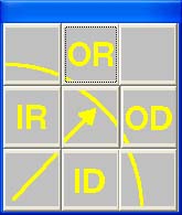 To measure
an Ellipse, press the Ellipse key < x > for the default
number of data points as set in System Options. Geomet will then prompt you for the type
of feature being measured, see figure at left. If you have
Auto Direction enabled, this
prompt will not appear.
To measure
an Ellipse, press the Ellipse key < x > for the default
number of data points as set in System Options. Geomet will then prompt you for the type
of feature being measured, see figure at left. If you have
Auto Direction enabled, this
prompt will not appear.
The default minimum number of points for an ellipse is 5, however we
suggest using a minimum of 16 when attempting to obtain a form value.