|
Introduction
The PMAC PC104 CMM Interface is the communication link between the Geomet
family of products and the motion controller for the DCC style CMM.
Installing the PMAC PC104 for the first time
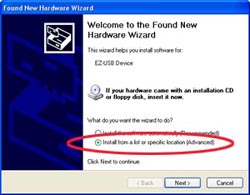
When you are required to load the PMAC motion control drivers for the first time, for
example on a new computer, there is a built in Add Hardware Wizard in Windows to assist
the installation. The Wizard will appear when you attach the USB cable between the PMAC
motion controller and the computer, see figure 1.
 |
 |
| figure 1, New Hardware Found |
figure 2, Select Search Options |
You will need the Geomet Installer CD to perform this installation. On the Found New
Hardware choose "Install from a list or specific location (Advanced)" and select
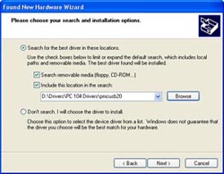
<Next>. The next page in the Wizard prompts for search locations, see figure 2.
Place a check next to both options and use the <Browse> button to locate the folder
\Drivers\PC 104 Drivers\pmcusb20 on the Geomet CD. Press the <Next> button.
 |
 |
| figure 3, Choose Driver |
figure 4,
Logo Testing |
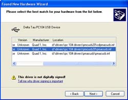
After the Wizard completes the search, a list will be displayed from which you can
choose which driver to install. Locate the driver in the folder ....\pmacusb20\pmacusb.inf
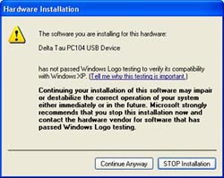
as shown in figure 3. Select <Next>. The Wizard will read the driver installation
script and display a confirmation page, see figure 4. Press <Continue
Anyway>.
 |
 |
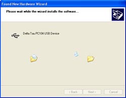
| figure 5, install Progress |
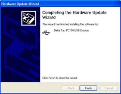
figure 6, Installation Complete |
The Wizard will display the installation progress page,
see figure 5. When the
driver installation is complete, the Wizard will display a confirmation page
select <Finish>, see
figure 6. To confirm the installation, use the Windows Device Manager.
Windows Device Manager
Under normal conditions, Geomet installs the proper files required for the PMAC PC104
card and establishes communications. Should a condition arise where the Windows system
does not recognize the USB connection to the PC104 a quick check using the Device Manager
can be used.
To launch the Device Manager, locate your Windows Control Panel (on XP, Start Menu→Control Panel) and locate "System". The System Properties tabbed dialog
appears which you would choose the "Hardware" tab. Next select the
<Device
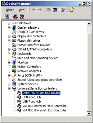
Manager> button and the Device Manager tool appears, see figure 7.
 |
|
figure 7, Windows Device Manager |
Expand the tree to show "Universal Serial Bus controllers". There should be
an entry for "Delta Tau PC104 USB Device" as shown highlighted in figure 7. If
an error with the installation has been noted, there will be a "?" next to the
name. In some cases, the device name will not be
displayed or has a generic name. In this case the name "Delta Tau...." will
not appear. If this condition exists it is possible the installation of the files has failed or
a conflict exists with another device. Contact Helmel support
for assistance.
Establishing Communications
The CMM Interface controller is designed to work with many communication formats, ISA
Bus, USB, or RS-232 just to name three. When the communications have not been previously
established, the user can set the communication mode by choosing [System→Interface
Configuration] from the main pull-down menus
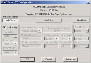
in Geomet, see figure 8.
 |
|
figure 8, PMAC Communications |
Setting USB Communications
Depress the button <In PC Bus> in the "Device Location" group and set
the check on USB Mode. To test the communications, press the <Ok> button and the
connection through the USB port will be tested. If successful a message will display
noting a connection has been made.
If communications could not be established please reference to the following chart.
|
Tctrl13.ocx PMAC PC104 Folder Installation
Version 6.3.16.4 |
| Loose Cable |
Check
that the USB cable is seated correctly at the computer and on the PMAC motion controller. |
| Power Connections |
Ensure
you have power supplied to the motion controller. The LED "D2 PWR" should be
green. |
| Required Software Files |
PMAC
PC104 requires the installation of software support files. These are:
pmac.dll
pmac.vxd
They are normally installed when the Geomet installation takes place. Depending on the
operating system they will be installed, see Table 1. |
| Device Manager |
Check
the system Device Manager to ensure the operating system recognizes the USB installation,
see
figure 2. |
|
NOTE: In all cases, cycle the
power to Geomet and the electronics cabinet. Windows offers many
tools to perform a diagnosis at startup which may detect, and
correct, problems within devices attached to the USB. |
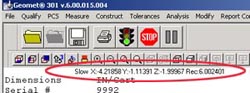
Interface Options
The CMM Interface has several options that must be set for proper operation. To
activate the setup tools you must first have the Interface Data Strip shown,
see
figure 9. If this data strip is not shown, refer to
Toolbar
Status.
 |
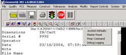 |
| figure 9, Interface Data Strip |
figure 10, Selecting Joystick defaults |
To activate the Joystick Default tool, position the mouse pointer over the data strip
and right-click to activate the sub-menu. see figure 9. Select [Joystick
Defaults], see figure 10.
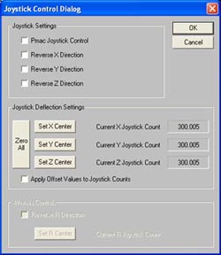
Depending on your Joystick series, see below,
you will have control over the directions. When a series 1 or 2 is installed
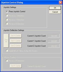
on your CMM, the setup tool will resemble figure 11. When the motion
controller, PMAC, has control over the joystick, the parameters and
behaviors are disabled and your setup tool will look like figure 12.
 |
 |
| figure 11, Joystick Defaults |
figure 12, PMAC Controlled Joysticks |
Setting Joystick Directions - Series 1 and 2
To establish the direction of motion relative to the deflection of the joysticks, there
are check boxes to reverse the direction of motion if required. For example, if the
joysticks are deflected in the +Y direction and the CMM moves in the -Y direction, place a
check next to the "Reverse Y Direction" label. As shown in figure 11, both the Y
and Z direction have been reversed.
Joystick Deflect Setting
These values are used primarily for testing and are not utilized by Geomet.
The joystick control has gone through a series of
engineering changes. It is important to understand which series your
joystick belongs too. Identifying which series you are using requires that
you shut down Geomet and the electronic cabinet. Remove the cable from the
joystick housing and matching the connector to the styles shown in figures
12, 13 and 14.
|
Geomet
Joystick Series Identification Table |
 |
 |
 |
|
Click here for a
larger Image |
Click here for a
larger Image |
Click here for
a larger Image |
|
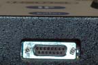
figure 13 |
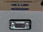
figure 14 |
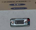
figure 15 |
| |
|
Series 1 |
Series 1, as shown in figure 13 has a
connector containing 15 pins in a double row. The joystick
connects to the game port of the Geomet computer system. |
|
Series 2 |
Series 2, as shown in figure 14 has a
connector containing 9 pins in a double row. The joystick
connects through a USB connection to the electronic cabinet to
an Interconnect card. From the Interconnect card, there is a
connection to the USB port on the Geomet computer system. The
Geomet system controlled the motion of the CMM by interpreting
the joystick deflections. |
|
Series 3 |
Series 3, as shown in figure 15 has a
connector containing 15 pins in a triple row. The joystick
connects through a USB connection to the electronic cabinet to a
Interconnect card. From the Interconnect card, there is a
connection to the USB port on the Geomet computer system. The
Geomet system controlled only the button presses and the PMAC
controlled the motion of the CMM by interpreting the joystick
deflections. |
Related Procedures:
Calibrate Joysticks
|


