|
Introduction
Using auto direction on 1D Points can lead to erroneous reported values if used
incorrectly. Auto direction relies on a smooth approach, from you the operator, in
capturing of a data point. The process of determining the approach vector involves the CMM
interface card (ProCounter, Tech 80 or PMAC) to maintain a rolling IJK vector based on the
last five reported values. These interface cards update the current position in the MCS on
a programmable time interval from 20 to 200 milliseconds.
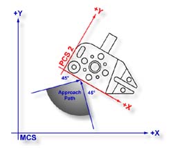 |
| figure 1, Auto Direction Approach Vector |
When you are approaching your work piece, it is required that you make contact while
remaining in a ±45° approach, see figure 1. In this example, if we remained in the
approach zone we will capture a data point that will be reported as a +Y point. If the
operator did not remain in the approach zone the 1D Point might report a + or - X Point
from which we will have to correct the probe compensation error. Most common occurrence of
a erroneous data point comes from operators who approach the surface, and then pause
during the approach and attempt to make contact under extremely slow speeds, which while
approaching causes variations in the path toward the surface.
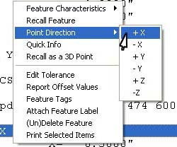 |
| figure 2, 1D Point Correction |
To correct the reported direction of a 1D Point, highlight the feature by left-clicking
on it, then right-click to bring up the feature menu, as shown in figure 2. Select
[Point
Direction] which will offer a sub-menu with all six probing directions available. Choose
the correct 1D Point direction and your part inspection will update with the correct 1D
Point. Note: Once a feature has been referenced it can not be changed or edited. For
example, if a feature was used in the construction of a PCS , it will be locked from
changes. This is identified by the inclusion of a ¹ next to the feature number, example
" 12¹ ".
Using Auto-Direction with multi-point features such as circle, lines and planes can
also incorrectly report feature characteristics. This occurs when capturing data points in
an inconsistent method or by capturing data points at a high rate. As previously
mentioned, the calculation of the direction vector for the probe works off the speed of
the interface and should that rate of point capture be to high, the changes in direction
going toward, then backing off the data point will create a poor direction vector.
Since touch probes can be effected by speed and our auto-direction tool is also
adversely effected by speed, we suggest the use of a smooth consistent approach speed and
rate when capturing data points.
To activate the Auto Direction sensing go to
System Options, <F9> and
locate the Auto Direction sensing key.
To activate, change the choice to 'Yes' next to the Auto
Direction sensing key.
During the inspection process you may require to control the Auto Direction sensing
manually. This can be accomplished through the Feature Measurement Toolbar or by pressing
the <u> key on the keyboard. The iconic button on the toolbar will indicate the
status of the sensing option. In figure 4, the button shows an "X" through the
button. This indicates that if the button was pressed, you will take sensing off.
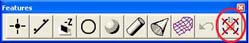 |
| figure 4, Auto Direction is ON. |
In figure 5, we see the iconic button shows no "X" over it indicating that if
you press the button, it will turn the sensing back on.
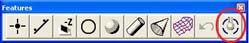 |
| figure 5, Auto Direction is OFF |
Although the visual appearance of these iconic button appears to be backward it
actually represents what the button will do should it be pressed. The button is not
designed to represent the current state of the Auto Direction Sensing.
|


