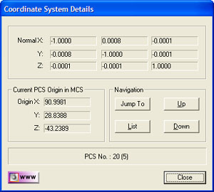
The PCS Viewer, when launched, displays the
Origin and Axis information for the current PCS in use. To navigate to
display another PCS, use the <Up> or <Down> buttons. To jump to a specific
PCS, use the <Jump To> button command.
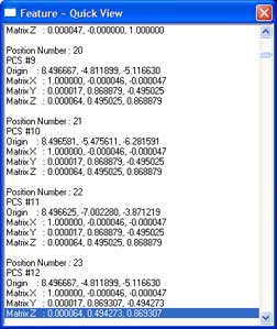
Viewing all PCSs in a report view can be accomplished
by pressing the <List> button command, see figure 2. The list command
will display PCSs #0 which is the
MCS to #404.
Within the list, PCSs are defined using two numbers.
The first is the "Position Number" which is its location or record number
within the array of coordinate systems. The other identifying number is its
"PCS #" or designated as a "ICS".
When a PCS has been established it is assigned a PCS
number, which is the recorded feature in the inspection report. When
building a PCS, you must establish the Primary (Orient), Secondary (Align)
and Tertiary (Origin) before a PCS number is assigned. When you have not
completed all required steps, the coordinate system is considered a Interim
Coordinate System (ICS). These coordinate systems are enforce when measuring
features. Geomet suppresses the display of results while a ICS is active.
The reported values are meaningless in there nature.
The use of the PCS Viewer and the PCS List helps to
identify problem coordinate systems that can occur during setup.