
|
|
CAD Graphics Display Point Style |
|

|

|
|
|
|
| |
| |
|
|
|
|
7.01.157 |
|
Geomet 101+, 301, 501 |
| |
|
|
|
|
| |
Definition |
| |
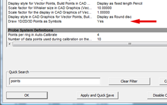
Points displayed in the CAD Graphics can be set to
display as traditional vertices or as unique symbols. |
| |
PCS Axis Style |
| |
Geomet CAD
Graphics supports two styles of Point styles.
These styles are a user preference and can be
set as a global setting in System Options.
Launch the System Options tool by pressing
the <F9> key. Enter "points" in the Quick Search
data field. Locate the entry "Draw 1D/2D/3D
Points as Symbols". |
 |
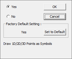
| To change the
Points between Vertices and symbols left-clicking on the
entry line. A popup tool will appear and by
left-clicking on the Yes followed by the <Ok>
button, the Points will be displayed as symbols
in CAD
Graphics. |
 |
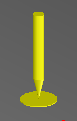
| When Symbols = No,
there are no differentiating identity between
1D, 2D and 3D Points. |
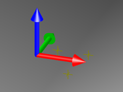 |
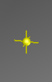
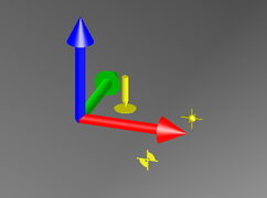
When Symbols =
Yes, you can clearly see the different points
and in the case of 1D Points, the direction.
 |
1D Point.
The arrow direction represents the probe
direction such as -Z Point. |
 |
2D Points.
Symbol is projected into the PCS Base
Plane. |
 |
3D Points.
Vertices with a shaded sphere in the
actual PCS position. |
|
 |
|
|
