 |
|
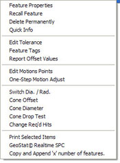
Cone Sub-Menu |
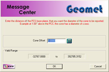
The Cone Offset command produces a reported diameter at a specified
distance from the PCS Base Plane. For example, what would the diameter on
the cone at –0.250” below the PCS? To obtain the value, highlight the cone
in the report and right click to activate the sub menu, choose [Cone
Offset].
Enter –0.250 in the Cone Offset Setup Tool, see figure 1, and
select <Ok>. The Offset Tool will then calculate the diameter
on the cone. There is a test to prevent entering a offset value that passes
the apex of the cone. The reported cone diameter is
the solution of a parallel plane with the current PCS intersecting the cone
at the specified offset.